tirsdag den 19. august 2014

Final Project - Lesson 6

Session 6

Date: 11/06 2014
Duration of activity: 10.15 - 14.30
Group members participating: Pætur Askildsen, Christian Jegstrup Hansen, Søren Gregersen, Søren Ditlev and Alexander Rasmussen


Goal

  • Solve gyro drift problems, or get closer to that goal
  • Implement bluetooth-enabled connection for car on the top of the tube for fine-tuning the PID constants.
  • Work on the accelerometer to understand it better and to use it as a long term parameter to avoid drift

Plan

To solve the gyro drift problem modification on the raw gyro data is needed. In this session we seek understand what causes the gyroscope to drift and find solutions online which can help us combat this problem.   

In lesson 5 in the course, we were to constructed a self balancing robot - segway. In that lesson we  implemented a Bluetooth controller to fine-tune the parameters of the PID controller on-the-fly. In lesson 5 it proved to be a very useful feature to have, so we plan to go back and look at our lesson 5 implementation of the Bluetooth connection transfer it to our car on the tube.

Results

Choice of parameters on-the-fly

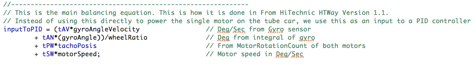
We rewrote our bluetooth-enabled PID constant fine tuning program from lesson 5 - Self-Balancing Robot [1] to be used to change the parameters which we needed in our TubeBalancing car program. The reason for using this method is, as lesson 5 put it:
During the development of a balancing robot a lot of adjustment of constants is needed. This can be done by editing the Java source code, compile and transfer it to the NXT before the next trial. To speed up this trial and error process a wireless communication could be established between PC and NXT so the constants of the program can be changed on-the-fly. [2].

We rewrote the PCcarController.java GUI LeJOS PC program to match our context, and the same with the BTcontrolledCar.java LeJOS NXT program. The programs can be found from our blog site.

Accelerometer and gyroscope deficiencies  

While Pætur, Christian and Søren D are working on the PID-controller, the balancing robot and trying to handle the drift from the gyroscope, Alex and Søren G are trying to solve the drifting problems using an accelerometer for the long term calculations on the orientation.
The problem with the gyroscope drift seems to arrive when the system has been running for several seconds. In the beginning of each run when the gyroscope has been calibrated, there seems to be no problem, and the car balances nicely on top of the tube. But already after 5-7 seconds after the launch, the gyroscope starts to drift, meaning that its offset is displaced a few degrees to the side. This means that the point that the car is trying to adjust to is continuously moving more and more to one side, resulting in the car’s eventual fall off the tube, even though it is actually still close to the reference point.

Figure 1: Rough and non-measured illustration of the drift of the gyroscope

We looked for different solutions on the drifting problem online, and found one, suggesting that an accelerometer is implemented to help the system knowing where the actual reference point is located. As accelerometer measures all forces working on the object it is very apt at detecting small changes, however because the accelerometer is so sensitive, very small disturbances may affect the system, this makes the accelerometer unsuitable for very precise systems (like our tube balancing robot). The gyroscope on the other hand, is very good at obtaining an accurate measurement that is not susceptible to external forces, but from another deficiency instead - drift. Drift is unavoidable because of how you determine angles with gyroscope data. This is done by obtaining angular velocity dec/sec form the gyro and then integrating this term by multiplying it with the measurement frequency. The result of that piece of math is a angle in degrees. By subtracting this angle from the last known angle of the system, you know how much the system have moved. The actual drift will be caused by the  inaccuracy of the gyro measurements and because we can not make contentious calculation of the gyro position but are limited to the code loop time. Therefore, over time, the gyroscope will drift slowly away from the reference point as shown in figure 1.
       

Complementary filter using Gyrometer and Accelerometer

The basic idea behind the complementary filter is to combine the strengths of the gyroscope and accelerometer respectively to produce a value that is both responsive, accurate and does not drift. In theory this is done by making the gyro measurements responsible for the short term changes to ensure high accuracy, and use the accelerometer for the long term changes to prevent drift.

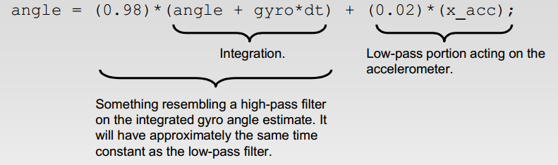
Figure 2: Complementary Filter

As shown in figure 2 [5], the complementary filter is composed of two filters. A high-pass filter concerning the gyro and low-pass filter concerning the accelerometer. The high-pass filter uses the angle previously calculated by the whole complementary filter algorithm,  and adds the angle currently obtained by the gyro. This value is heavily weighted (0.98) to give it a to give it a lot of influence in the the short term. The low-pass portion of the complementary filter uses the accelerometer data weight it very lowly (0.02) so that it does only have a very low immediate influence. However since the low-pass portion is added to rest of the algorithm it will have a significant influence over time as shown below [5]:

   
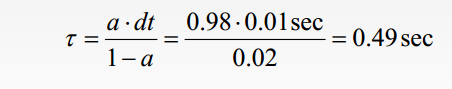
Figure 3: The weight of the accelerometer and gyro

As seen in the statement  above. The gyro will have the most influence in measurement under half second ago, but the gyro will have be the most influential in anything above. This value can of course be tweaked to give the gyro or the accelerometer more influence.  
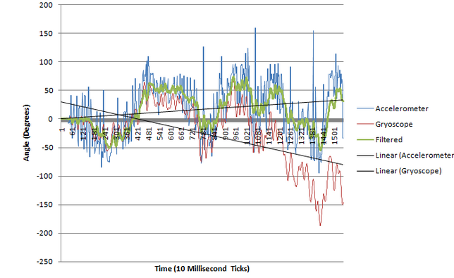
Figure 4: Complementary filter readings

As shown by the graph above [6]. The accelerometer data(blue) is very jumpy, whereas the more accurate gyro data (red) drifts over time. However the complementary filter data(green) is stable and does not drift. This is in essence what we hope to achieve by implementing a complementary filter.

Skrive noget om, hvordan vi har udregnet de forskellige faktorer, samt code-snippets.

The formula for the complementary filter looks like this:
angle = 0.98 (angle + gyrData dt)+0.02(accData)

The angle is calculated from a the gyroscope and accelerometer data which weighs respectively 98 % and 2 %.
The gyrData constant is the angular velocity from the gyroscope, measured in degress pr second, and can be found with the method getAngularVelocity() already a part of the class GyroSensor(). The dt constant is the sample period for the system. We have a sample rate of 100 Hz which gives a sample period of 0,01 second. By integrating it with the dt constant we get the angle of the gyroscope at time t.

Working with the Accelerometer

The initial plan was to make a vector comprised of the x- and y-axis of the accelerometer, since we do not use the z-axis we just plainly omitted it. By taking the absolute value axis and adding them to one another we were able to find a unified number that should best represent the car's movement on the tube.  

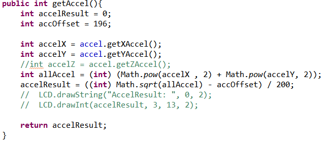
Figure 5: Movement vector
Figure 6: The different axes on the Hitechnics Accelerometer [4].

Figure 7: The axes for the HiTechnics accelerometer seen on our car.

Conclusion

In this session we were able to gain an understanding of the complementary filter, which we can hopefully implement in the future to reduce or remove drift. We have made a movement vector by combining the x- and y-axis of the accelerometer, which we plan to use in the complementary filter. However we are not sure if it is possible to use a combined axis vector, this we will have to test in an upcoming session.

Plan for next session(s)

Get a bluetooth connection from a PC to the tube balancer going, so that we will be able to adjust the PID and 2-parameter values when it is running.
Implement and continue to work on the complementary filter.

References


tirsdag den 10. juni 2014

Final Project - Lesson 5

Lesson 5


Date: 10/06 2014
Duration of activity: 10.15 - 13.30
Group members participating: Pætur Askildsen, Søren Ditlev and Alexander Rasmussen


Goal

  • Finish the code for the remote controller
  • Rebuild the remote controller to be more sturdy.
  • Make the car inside the tube four-wheel driven.

Plan

Figure out why the remote controlled car only drives forwards even though it is supposed to drive backwards and fix it.
The original remote controller was just a quick mock-up and we want to build a rigid remote control.
During last lesson we experienced that the car inside the tube had difficulties moving when turning upside down. The reason for this is that the car was rear-wheel driven. Therefore we plan to rebuild the car to make it four-wheel driven by adding gears.

Results

Fix the code of the remote controlled car

The problem regarding the remote controller that the NXT started ticking and the program would not start was quickly fixed. The problem was that some variables that should be turned from integers to floats were still integers and was therefore causing problems.
When this problem was fixed the program would run again, but the car would still only drive forwards. This problem was also easily fixed.

Figure 1: Code snippet of if-statement in RCCMain.

The if-statement in figure 1 is the reason why the car would only drive forwards. The problem with the if-statement is that when the speed value is positive the method Car.forward() is called with a positive value and therefore it drives forwards. But if the speed value is negative the method Car.backward() is called with a negative value, this results in a negative speed backwards which is the same as positive speed forwards. This was the reason why the car could only drive forwards. To resolve this the if-statement was removed and replaced with the code snippet i figure 2.

Figure 2: Code snippet of fixed code in RCCMain.

Rebuilding the remote controller and the BT controlled car

After fixing the code we were able to rebuild the BT controlled car so that it is now four wheel driven instead of only rear wheel driven. The four-wheel drive was built using three gears in each side of the car to connect the wheels to each other as it can be seen in figure 3. This gearing made the car able to drive even though it is upside down as the video shows [1]. Meanwhile we rebuilt the remote controlled car, we also rebuilt the remote controller to make it more sturdy. The redesigned remote controller can be seen in figure 4.
Figure 3: The gearing to make the remote controlled car four wheel driven.

Figure 4: The rebuilt remote controller.

Conclusion

We have fixed the problem with the remote controlled car only driving forwards, which now makes it capable of driving both forwards and backwards. The remote controlled car has also been rebuilt, so that it now has four-wheel drive, this is due to the robot not being able keep traction when driving with only front-wheel drive.The remote controller has also been rebuilt.

Plan for next session(s)

Get readings from the gyro and accelerometer. Combine the readings into a complementary filter to conquer the gyro drift.

References

[1] Video of rebuilt car driving inside the tube, http://goo.gl/V1TKIQ

mandag den 2. juni 2014

Final Project - Lesson 4

Lesson 4

Date: 02/06 2014
Duration of activity: 09.15 - 15.45
Group members participating: Pætur Askildsen, Christian Hansen, Søren Gregersen, Søren Ditlev and Alexander Rasmussen


Goal

  • Make the car balance on top of the tube.
  • Finish the remote controller.

Plan
Adjust the code so that the balancing robot only uses the gyro readings and not the tacho counter (we have a hypothesis that the tacho counter is only necessary when the robot, in the LegWay, needs to balance on the floor). Tacho counter may not be needed since we want to make less subtle movements, in order to react on the tubes movements. The PID parameters should also be tuned.

We want to get the remote controller to communicate with the car inside the tube using Bluetooth. Hopefully the remote controller can be finished today.
The steps should be prioritized as follows, so we start out simple:
  1. Make the car balance on top of the tube by itself.
    1. Adjust PID (maybe do this through bluetooth to ease adjustment overhead)
    2. Try removing tacho counter and rely solely on gyro.
  2. When this works, add the remotely controlled car inside the tube to also be in to the setup.
  3. Fine tune the speed of the car inside the tube (the faster it can drive, the more difficult we presume it will be for the TubeBalancingCar to keep balance on top of the tube).

Results

Tube Balancing Robot

The NXC program for the HTWay [1] (HiTechnics legway) does not use a PID controller. They instead use 4 variables to control the two motor powers of the HTWay, which in our example only will be one motor power, since we only have one motor. With their own words:

“To calculate the power these variables are multiplied by respective constants in a four term linear equation, the result being the power needed for the robot to stay balanced. The trick to making this all work, is finding the right constants.” [2].

The 4 variables the NXC program uses to balance the LegWay can be seen here, though translated into Java:

Last time we fed the result of this linear equation into a PID controller. Today we will take one step back, and use this variable directly to control the motor power, instead of, as the variable names says, inputToPID. We want to check that a PID really is necessary for a tube-balancing robot. We will also look at if all 4 parameters are needed.

Fine tuning the four parameters, the non-PID way

First test

We change the parameter tAV, the paramter controlling the influence of the angle velocity, gyroAngleVelocity, from 0,475 to 0,7.

Result: The car still does not react and drive fast enough, not enough motor power, when the car is far around on the tube. This points in the direction that we might need a PID, or at least the Integral term, so the longer the car falls off the tube in one direction, the more speeds it gets. But we try on without a PID.

Second test

As we needed more power, we try out multiplying the power by 2:

int power=  (int) inputToPID * 2;

Result: The car drives faster, but this also makes the tube roll faster. The car can still not get up on the tube again when about to fall off.

Third test

We give the car bigger wheels, from the small ones we started with to the big ones with white inside of wheel.

Result: The same as in the second test. The car can still not get up on the tube again when about to fall off. We also notice and discuss, that since the LegWay uses the tacho counter, it starts driving even when the car seems to be perfectly balanced on top of the tube, or just on the ground and give it a push, and the car drives off. This leads us to our fourth test:

Fourth test

We try to remove the two parameters, motor speed deg/sec and tachocount to only use the gyro. To do this the
private float tPW = 0.042f;
private float tSW = 0.05f
are set to 0 so only the gyroAngle and gyroAngularVelocity are used to calculate the motor power.

After further reading on the HTWay, they also say they use the motorSpeed and motorPosition to keep the robot in place:

So what about the two motor terms? Well if the robot is perfectly upright and not falling but the robot is 100 degrees further forward than desired, in that case motorPos will be 100. [...]  The motorSpeed term works in sort of the the same way as motorPos. [2]

Therefore it was good that we removed those terms, as keeping the robot in place is not the highest priority for our robot. The highest priority is for the robot to stay on the tube. Possible future work could be to determine the feasibility of using a behaviour-based architecture for keeping the robot in place while staying on the tube [3].

Result: The car still drives off, and starts to drive faster and faster when placed on the floor. We conclude therefore that it is not the motor parameters but the gyro sensor which drifts from the initial offset, which makes the car drive off. We need to make up for that either in the build of the robot or the code to deal with gyro drift.

Fifth test - Gyro drift due to motor interruptions?

Søren found from a forum, that if the HiTechnic gyro sensor offset is calibrated when the motor is off, when the motor is turned on the electromagnetic field of the now turned on motor will cause the gyro sensor to drift [4]. To try to fix this, we increase the height of the placement of the gyro sensor on the car, so it hopefully will not get affected by the motor.

Figure 8: The car with the gyro sensor mounted higher.

Another finding on this forum is that when the gyro sensor gets hot it will get different readings and thus drift. We found that turning on the gyro over time it would drift, presumably because it gets hot, but then when it was hot we reset the program thus recalibrating the gyro sensor and then it didn’t start driving when placed on a flat surface, the floor (gyro sensor drifting).

That the motors affect the gyro sensor was already thought of in the code we made last time, as the motor are activated by calling Car.stop() right before the calibration of the gyro sensor:

// Ensure that the motor controller is active since this affects the gyro values.
Car.stop();

However it seems that using Car.stop(); alone does not prevent drift.

Result: Now with the higher placed gyro sensor, finally the car doesn’t run off so immediately when placed on the ground with the same code as when the gyro sensor was placed lower. After a talk with Ole we realized that this however could also just be because we stabilized the gyro sensor more in the LEGO attachment construction than it is the height difference making the gyro sensor more stable. However, when given a push, the car does slowly crawl in one direction, but not as fast and accelerating as before. A conclusion is therefore that the placement of the gyro sensor more stable results in a not so drifting gyro. Some anti-drifting still needs to be implemented though. It is however much better now.

A finding is also that Car.stop() is not a good way to ensure that the motors are active before calibrating the gyro sensor, or that this approach does not fix the gyro drift problem.

The results from this, that we need to conquer gyro drift, is also to take a step back and do some experiments with the gyro sensor. Søren G and Alex were put on this task 11.41.

Now that the tube balancing car does not drive off when placed on the ground, we try again to test it on top of the tube. It however still falls off when the tube starts rolling and accelerating. The car needs to accelerate more.

Sixth test - Fine tuning tAV and tAN and gyro drift

Since the gyro sensor drifts significantly less, while Alex and Søren works on reducing gyro drift Søren and Christian will finetune the two parameters tAV and tAN respectively controlling the influence of the angular velocity and the gyro angle on the power to the motors.

We however, end up with going back to a PID because the car needs much power to avoid falling off the tube but this also happens fast, so the car reacts violently just using a linear equation to power the motors.

We first started out with only a P-controller, and found from (2.0 → 1.0 → 0.5) that kP= 0.5f worked well: the car did not oscillate violently. We then tried to make PI- controller with kP = 0.5f and kI = 0.5f. This made the car drive back and forth quick. We then reduced kI to 0.05f. This was better, but the gyro still drifts.

After writing to the LCD display both the angular velocity and the angle we found that the angle kept increasing.

Remote controller

The remote controller uses the tacho counter and this value from the tacho counter is mapped to speed using the code in figure 9. The spam of the speed is between -100 and 100 which means power of 100% backwards and 100% forwards respectively.
Figure 9: Code snippet of tacho counter mapped to speed

The calculated speed is sent to the car inside the tube using bluetooth communication and today we managed to get the bluetooth communication to work. Even though the spam of the speed was between -100 and 100, and the bluetooth communication worked, the car could only drive forwards even though it was supposed to drive backwards.
The reason why the car only drove forwards could be that the speed was converted from float values to integer values. We tried change the speed value to integer values, so that it never is a float value. This task bigger than expected and it was revoked. Unfortunately something went wrong, the NXT started ticking and the program would not start. This resulted in a little tension and we have to fix it as the first thing next session.

When we tested the remote controller and the remote controlled car inside the tube, we saw that the car would drive until it turned upside down and then it could not move, even assumingly was built to drive upside down. A video of the test can be seen here [5].
The reason that the car does not drive up side down is that it is two-wheel driven.

Conclusion
We have carried out a series of tests to make the robot balance on top of the tube. In this process we discovered a phenomenon called ” gyroscopic drift”. We played a bit around with different things that might affect the gyro drift and made a few configurations to accommodate gyro measurement inaccuracies. Furthermore the remote controller is nearly fully functional, except that it at the moment only drives in one direction.
Plan for next session(s)

  • Work on reducing gyro drift.
  • Fix the remote controller and figure out why the remote controlled car only drives forwards and fix this as well.
  • Rebuild the remote controlled car, so that it is four-wheel driven and can drive upside down.

References
[1] HiTechnic HTWay Version 1.1 code, http://www.hitechnic.com/upload/786-HTWayC.nxc
[2] HiTechnic’s HTWay, http://www.hitechnic.com/blog/gyro-sensor/htway/
[3] http://www.lejos.org/nxt/nxj/tutorial/Behaviors/BehaviorProgramming.htm
[4] http://www.lejos.org/forum/viewtopic.php?f=7&t=4656 
[5] Video of remote controlled driving inside the tube, http://goo.gl/QVqfGO.